
What this guide covers
This is a field guide to the AMI Aptio firmware on the tested Core i3-1215U EQi12, not a generic list of settings copied from another mini PC. We photographed the firmware page by page before changing it, recorded BIOS EQI12D405 on the fully inventoried unit, and then verified the settings that mattered through Windows, Ubuntu Live, Wake-on-LAN and physical power-cycle tests.
The purpose is simple: make virtualization, remote wake and automatic recovery predictable without changing unrelated firmware values. BIOS revisions can move or rename menus. Photograph every original page, change one value at a time and keep a keyboard and display available until the configuration is proven.
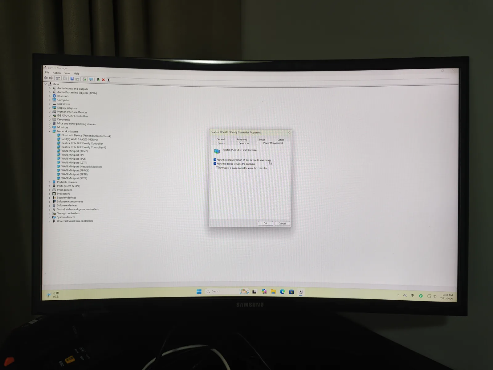
Before changing anything
Use a phone camera rather than expecting the firmware to save screenshots. Hold the camera square to the monitor, make every value readable and capture the complete page title. If a page scrolls, photograph the top and bottom with one overlapping row. Record the date, device ID and BIOS revision outside the image.
Do not load Optimized Defaults on a working server just to make the screens match this guide. That can change boot mode, storage behavior, Secure Boot and power settings together. If BitLocker or device encryption is active, save the recovery key before changing Secure Boot, TPM/PTT or boot configuration.
The complete source batch includes Main, Advanced, Chipset, Security and Boot pages. The web images below are representative editorial copies; the full-resolution originals remain in the evidence archive.
Intel Virtualization Technology / VT-x
VT-x allows the processor to run virtual machines and is required by Hyper-V and the WSL2 backend used by Docker Desktop. On an AMI BIOS it is commonly under Advanced → CPU Configuration, although the exact wording can change.
Select Intel (VMX) Virtualization Technology or Intel Virtualization Technology and verify that it is Enabled. After Windows starts, Task Manager → Performance → CPU should report Virtualization: Enabled. For this build, successful WSL2 and Docker operation provided an application-level check in addition to the firmware page.
Do not disable Secure Boot merely to enable virtualization. They serve different purposes and can operate together.
VT-d / directed I/O
VT-d is Intel’s directed-I/O virtualization feature. On this EQi12 it was found under the Chipset area rather than beside the CPU virtualization control. The firmware page reported VT-d as supported and showed the selectable value as Enabled.
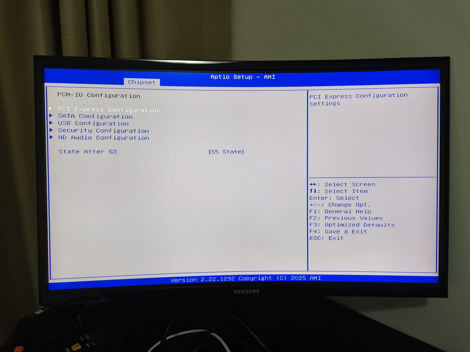
VT-d being enabled is useful for virtualization and device-assignment plans, but the setting itself is not the end of verification. The operating system still decides how devices are grouped and exposed. For the tested Windows/WSL2 stack, enabled VT-d was sufficient to continue with the intended build.
State After G3: automatic boot when power returns
State After G3 controls what the PC does after complete loss of AC power. On this BIOS it appeared under the Chipset/PCH-I/O path and offered:
- S0 State — boot into the working state when power returns.
- S5 State — remain shut down when power returns.
For an unattended server we selected S0 State. Save the page, exit, then re-enter the BIOS once and confirm the value persisted. Only after that should you remove input power for the physical test.
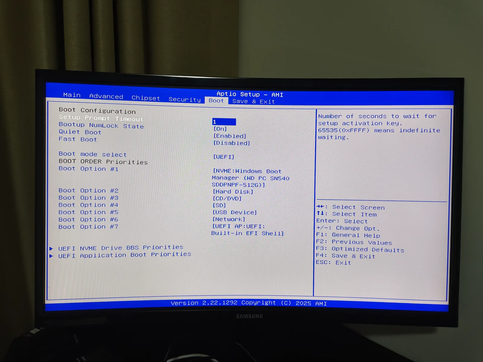
The finished EQi12 booted automatically in three out of three AC-return cycles. Jellyfin became available in about 40.77 seconds on average. That result links the menu setting to actual behavior; a photograph of S0 without a power cycle would prove only that the option exists.
Automatic boot is not a substitute for a UPS. It restores availability after power returns but does not protect an in-progress write from the interruption.
ACPI sleep and hibernation
The ACPI page exposed hibernation and S3 (Suspend to RAM). S3 preserves memory while most of the system sleeps. It is useful when rapid wake matters, but it also depends on firmware, the Windows power model, network driver settings and the active Ethernet port.
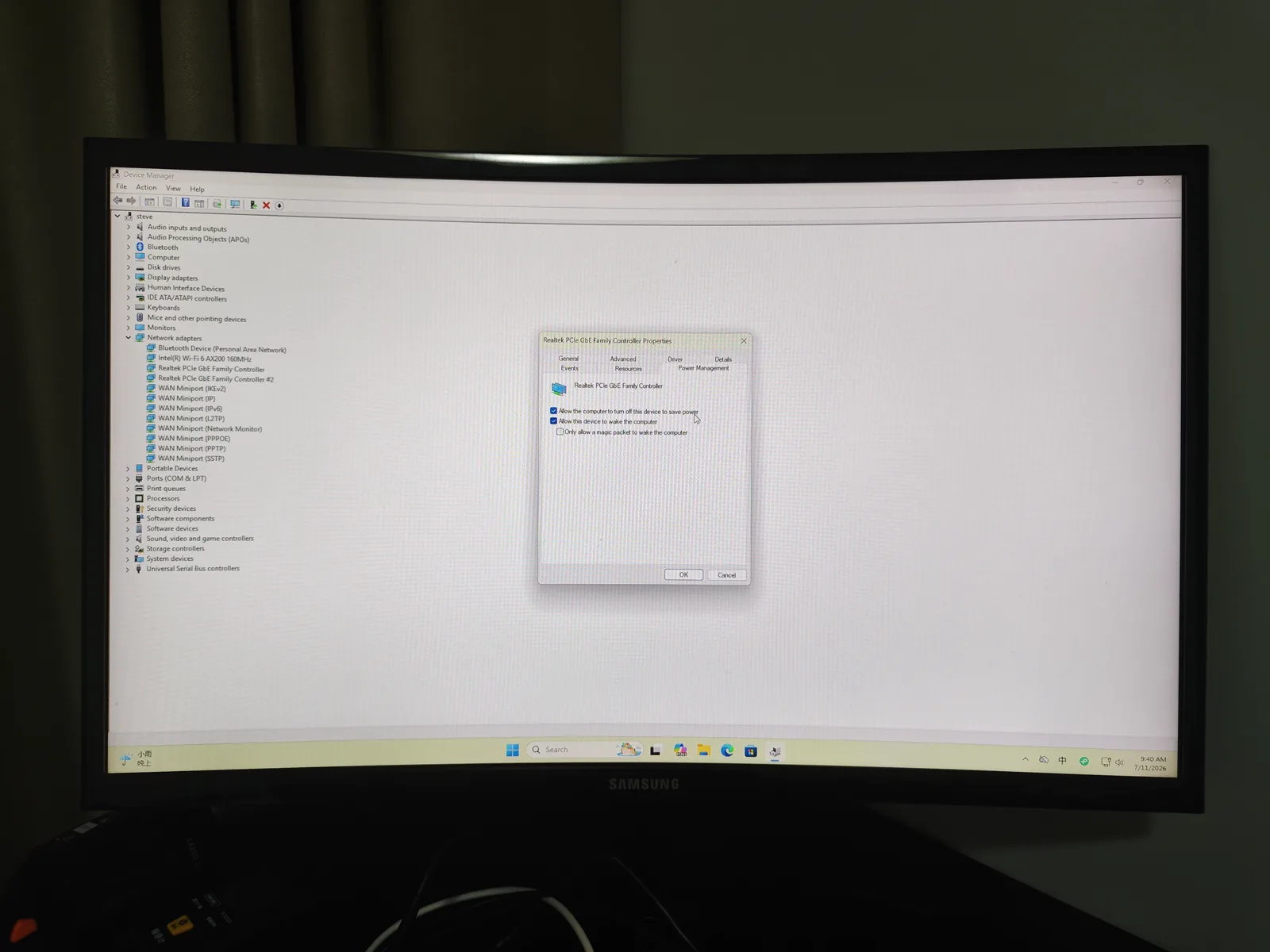
On this unit, S3 Wake-on-LAN worked four times in five cycles. Shutdown WOL worked five times in five. Both states read about 1W on the whole-watt meter. With no measured standby advantage and a less consistent wake result, normal shutdown plus WOL is the preferred unattended state.
Secure Boot, TPM/PTT and UEFI
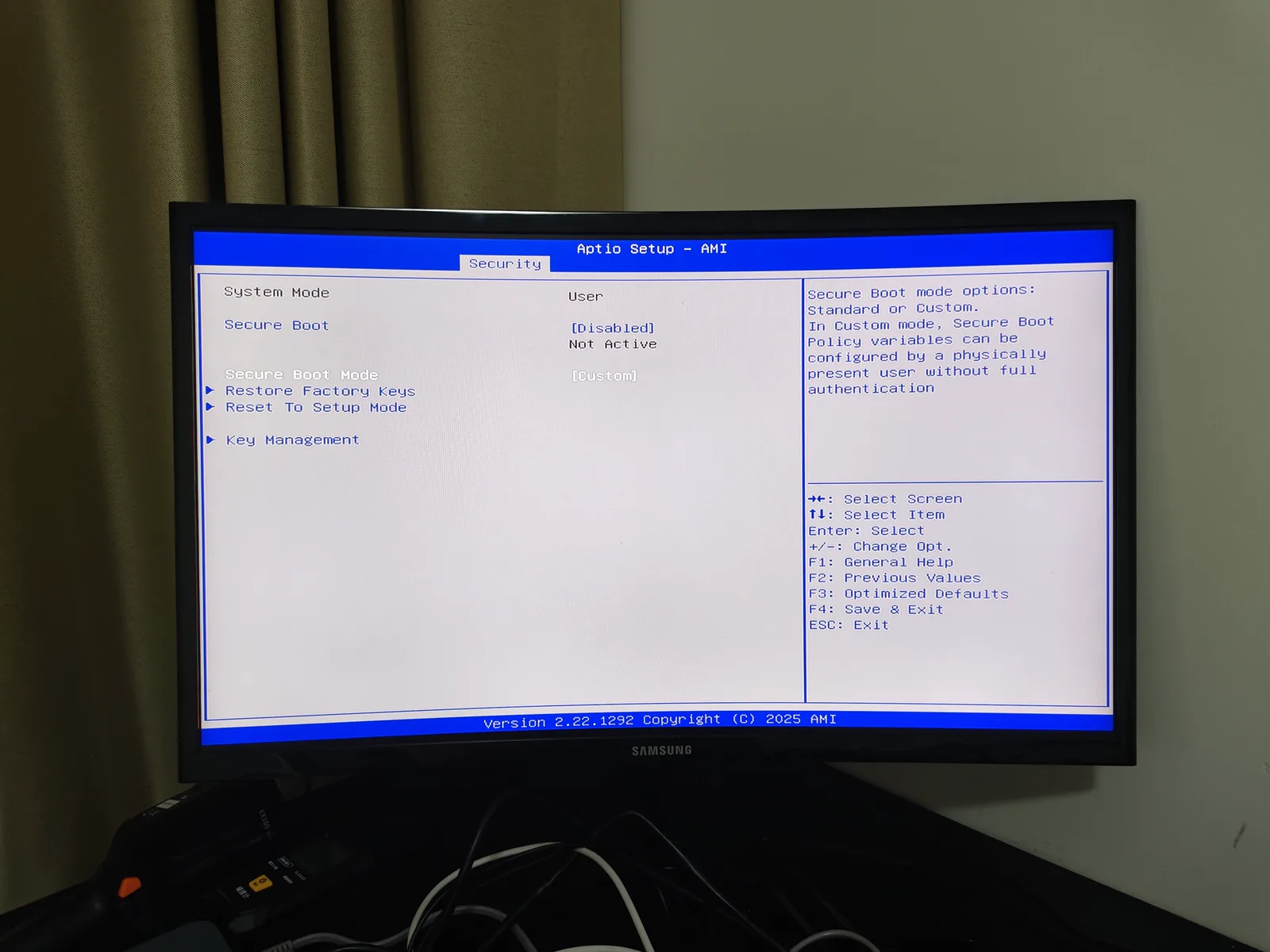
Modern Windows security depends on the relationship between UEFI boot, Secure Boot and the firmware TPM. The relevant EQi12 pages are under Security, Trusted Computing, PCH-FW Configuration and Boot, depending on the control.
For a normal Windows 11 server:
- keep UEFI boot active;
- leave CSM disabled unless a specific legacy device requires it;
- retain Secure Boot when the installation and drivers support it;
- retain Intel PTT/TPM for Windows security;
- verify BitLocker or device-encryption recovery information first.
An old virtualization tutorial may tell you to disable Secure Boot. That is not a general requirement for WSL2, Docker Desktop or Intel virtualization on this system.
Boot order and removable media
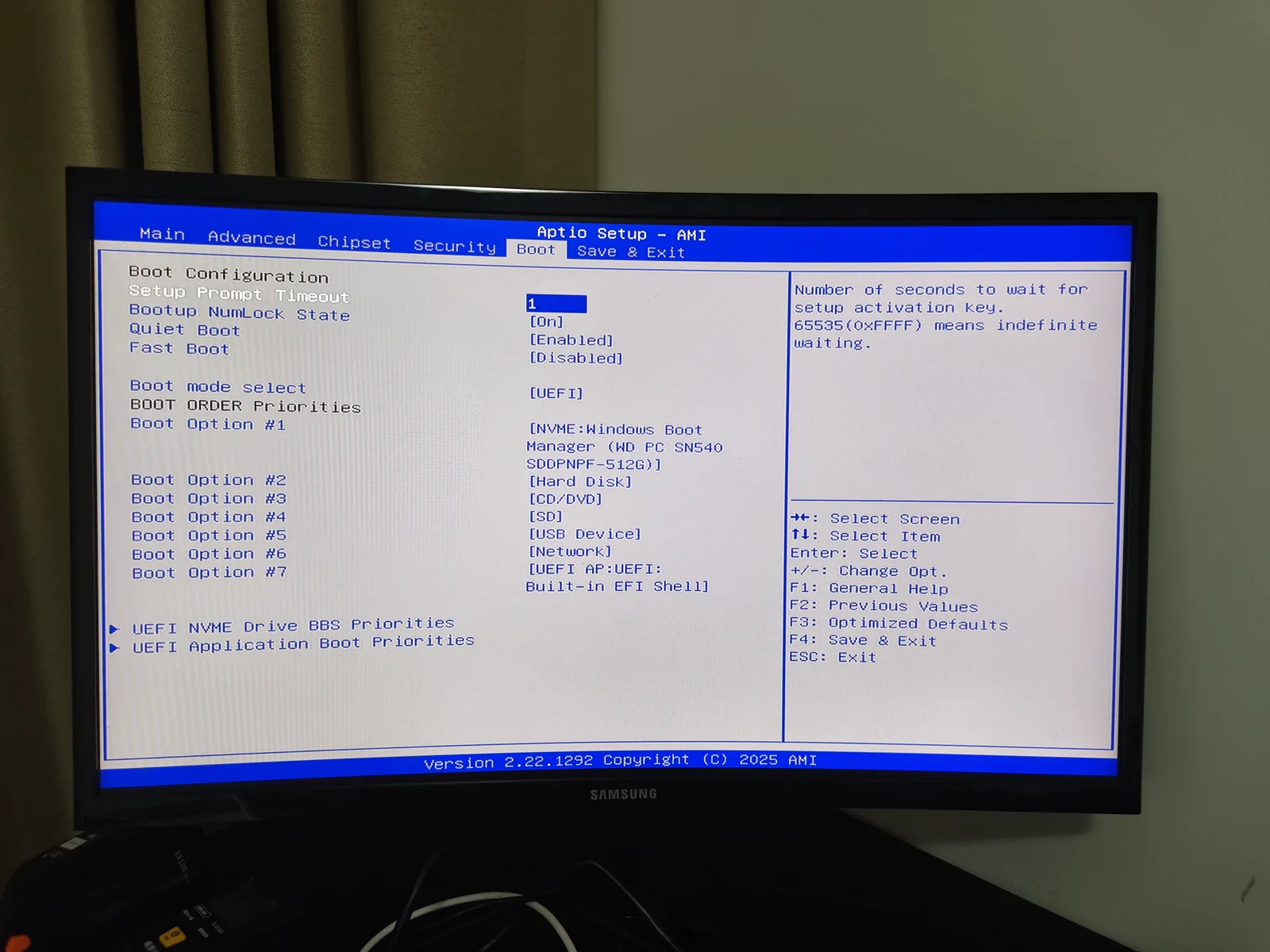
The Boot page determines whether the internal Windows Boot Manager, a Live USB or another device starts first. For one-time Ubuntu Live testing, use the F7 boot menu rather than permanently moving USB above the internal SSD. This reduces the chance that an unattended server later boots from a forgotten recovery drive.
After any boot-mode change, confirm that Windows starts, the NVMe drive remains visible and Secure Boot reports the expected state. A successful save operation is not evidence that the installed operating system can boot under the new mode.
Thermal and hardware-monitor pages
The firmware also exposes hardware-monitor and thermal sections. Photograph their defaults, especially any fan-control or power-limit values, but do not tune them while also changing virtualization or recovery behavior. One variable at a time makes a failure diagnosable.
For this review, thermal behavior was evaluated in Windows with monitoring and thermal images. No firmware fan curve was changed to create a more favorable result.
Wake-on-LAN is a chain, not one BIOS switch
This firmware did not present one obvious top-level Wake on LAN toggle that completed the job by itself. Working WOL required the connected Realtek controller, its Windows driver settings, Fast Startup and the target MAC address to agree.
In Windows Device Manager, enable Wake on Magic Packet and Shutdown Wake-On-Lan on the connected adapter. Under Power Management, allow the device to wake the computer and restrict wake to a magic packet. Disable Windows Fast Startup for shutdown testing. Because the EQi12 has two similar Realtek names, first map each one to a physical jack.
The Realtek Wake-on-LAN guide contains the Windows path. Firmware documentation and the Windows configuration should remain linked in the server record so a future driver update does not leave half of the chain undocumented.
Save, re-enter and test
After changing one value:
- photograph the final page;
- use Save Changes and Exit;
- allow Windows to boot once;
- re-enter BIOS and confirm the value persisted;
- return to Windows and verify network, storage and services;
- perform at least three cycles of the behavior the setting controls;
- retain failed cycles and event logs.
For State After G3, remove power only after Windows has shut down safely during setup. For the actual recovery test, record the full sequence from power removal to restored application availability. For WOL, send the packet from a second device and time to a known endpoint instead of stopping when the power LED turns on.
Settings summary for this build
| Setting or page | Tested choice / finding | Why it matters |
|---|---|---|
| Intel Virtualization Technology | Enabled | WSL2 and Docker backend |
| VT-d | Supported and Enabled | directed-I/O virtualization support |
| State After G3 | S0 State | automatic boot after restored power |
| ACPI sleep | S3 available | tested, but WOL was 4/5 |
| Shutdown WOL | Windows driver + Fast Startup configuration | passed 5/5 |
| UEFI / boot | modern Windows path retained | predictable secure boot |
| Secure Boot / PTT | documented before change | Windows security and recovery |
Recovery if a change prevents boot
First remove external drives and use the one-time boot menu to select Windows Boot Manager. If Windows asks for a BitLocker recovery key after a security change, use the saved key rather than repeatedly changing TPM settings. If the display stays blank, disconnect power, wait, reconnect and try the documented default display output.
Avoid clearing TPM, deleting Secure Boot keys or loading every default as the first response. Those actions can make recovery harder. Use the before photographs to reverse only the most recent change.
Bottom line
EQI12D405 exposes the firmware controls needed for the tested Windows home-server build. VT-d was enabled, S3 was available and State After G3 could place the machine in S0 after restored power. The important proof came after the menu: three AC-return recoveries passed, shutdown WOL passed five cycles and S3 WOL exposed one failure. Configure the BIOS narrowly, preserve the original pages and judge each setting by the behavior it produces.
Continue with the Windows home-server build for the end-to-end configuration, the AC power recovery guide for the physical cycle procedure, and the AMI BIOS State After G3 guide for a detailed explanation of every G3 recovery option.