
What is the G3 state?
In the ACPI power management specification, G3 is the Mechanical Off state. It means the system has been completely disconnected from AC power — no standby voltage, no RTC power from the main supply, and no ability to respond to any event until power returns.
When power is restored to a system in G3, the firmware must decide what to do. That decision is controlled by the State After G3 setting in the BIOS. Different manufacturers label it differently, but the behavior is the same concept across all AMI Aptio firmware.
ACPI power states at a glance
| State | Name | What it means |
|---|---|---|
| S0 | Working | System is running normally |
| S3 | Suspend to RAM | Memory powered, most hardware off |
| S4 | Hibernation | Memory saved to disk, system powered off |
| S5 | Soft Off | System shut down, but standby power available |
| G3 | Mechanical Off | No power at all, AC disconnected |
State After G3 only applies when the system transitions from G3 (no power) back to a powered state. It does not affect S3 wake, S4 resume, or normal S5 soft-off behavior.
What each option does
AMI BIOS implementations vary, but the most common options are:
S0 State (Power On)
The system boots immediately when AC power returns. It goes through the normal POST sequence and enters the working state without any user interaction. This is the correct setting for an unattended home server that must be available after a power outage.
S5 State (Power Off / Stay Off)
The system remains shut down when power returns. Someone must press the power button or send a Wake-on-LAN magic packet to start it. Use this when the server should not restart automatically — for example, after maintenance shutdowns or in environments where an unexpected restart is unsafe.
S4 State (Hibernate)
If the operating system created a hibernation image before the power loss, the firmware attempts to restore from that image when power returns. This preserves the exact session state but depends on a valid hibernation file existing on disk. Most home servers do not use hibernation, so this option is rarely useful for always-on deployments.
Last State (Remember)
The firmware records whether the system was in S0 (on) or S5 (off) before the power loss, and returns to that same state when power returns. If the server was running, it boots. If someone had shut it down before the outage, it stays off.
This sounds ideal but has a subtle problem: if the system was in the middle of a shutdown sequence when power was lost, the recorded state may be ambiguous.
Where to find the setting in AMI BIOS
The path varies by manufacturer and firmware revision. Common locations on AMI Aptio firmware:
| Typical path | Found on |
|---|---|
| Chipset → PCH-IO Configuration → State After G3 | Beelink, GMKtec mini PCs |
| Advanced → ACPI Settings → Restore AC Power Loss | Some desktop boards |
| Power Management → AC Power Recovery | Industrial and thin-client boards |
| Advanced → APM Configuration → After Power Failure | Some ASUS and ASRock boards |
The setting name is also inconsistent:
- State After G3 — AMI’s most common label
- Restore AC Power Loss — common on desktop boards
- AC Power Recovery — used by some OEMs
- After Power Failure — alternative label
- Power On After Shutdown — less common but functionally identical
All of these control the same behavior. If you cannot find the setting, check the Chipset and Power Management sections first.
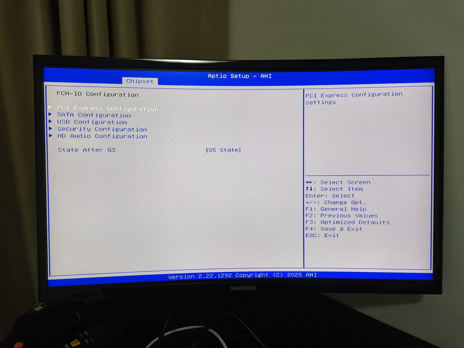
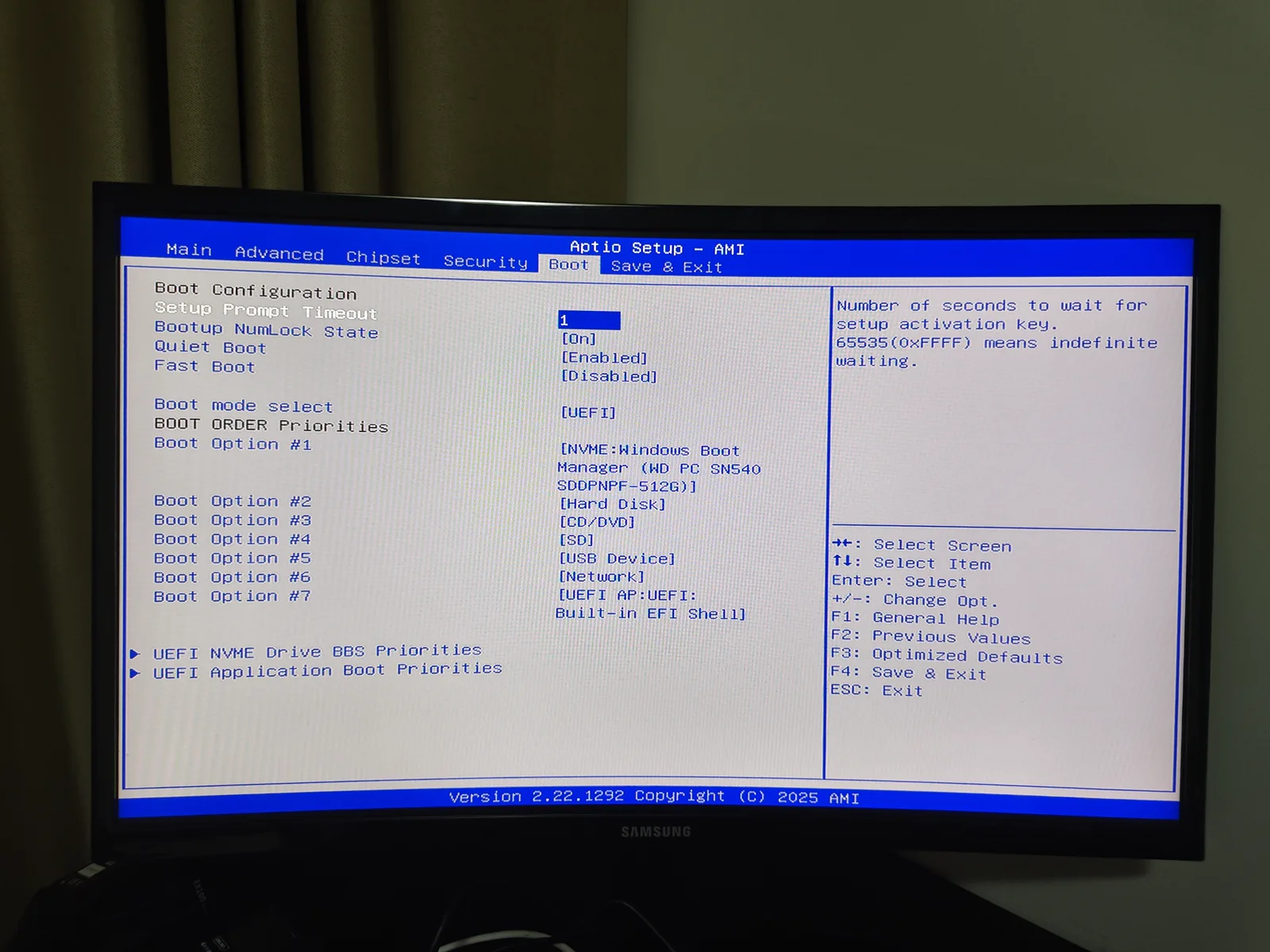
How to configure it for a home server
Step 1: photograph the current BIOS
Before changing anything, use your phone to photograph the current firmware page. Record the BIOS version, date and the exact menu path. If a change prevents boot, you need the photographs to reverse it.
Step 2: change the value
Enter the BIOS during boot (usually Del or F2). Navigate to the State After G3 setting. Select S0 State for automatic boot on power return. Save changes and exit.
Step 3: verify the value persisted
After Windows or Linux starts, reboot and re-enter the BIOS. Confirm that State After G3 still shows S0 State. Some firmware revisions reset to defaults after the first save, especially on mini PCs with modified BIOS builds.
Step 4: test with physical power removal
Do not skip this step. A setting that persists in the BIOS menu does not necessarily work in practice.
- Start from a healthy, fully booted system with all services running.
- Remove AC power completely (unplug or use a switched PDU).
- Wait until all LEDs are off and the Ethernet link light has extinguished.
- Restore AC power.
- Time how long until the system boots and the required service responds.
- Repeat at least three times.
Step 5: record the result
| Cycle | Auto-booted | Network ready | Service ready | Time to service |
|---|---|---|---|---|
| 1 | Pass/Fail | Seconds | Seconds | mm:ss |
| 2 | Pass/Fail | Seconds | Seconds | mm:ss |
| 3 | Pass/Fail | Seconds | Seconds | mm:ss |
If any cycle fails, retain the event logs and video evidence before retrying.
Tested result: Beelink EQi12 on AMI Aptio
On the tested Beelink EQi12 with BIOS revision EQI12D405, State After G3 was located under the Chipset/PCH-I/O path. The available options were S0 State and S5 State.
After setting S0 State and verifying persistence:
- All three AC-return cycles booted automatically.
- Jellyfin became available in approximately 40.77 seconds on average.
- The system required no button press or keyboard input.
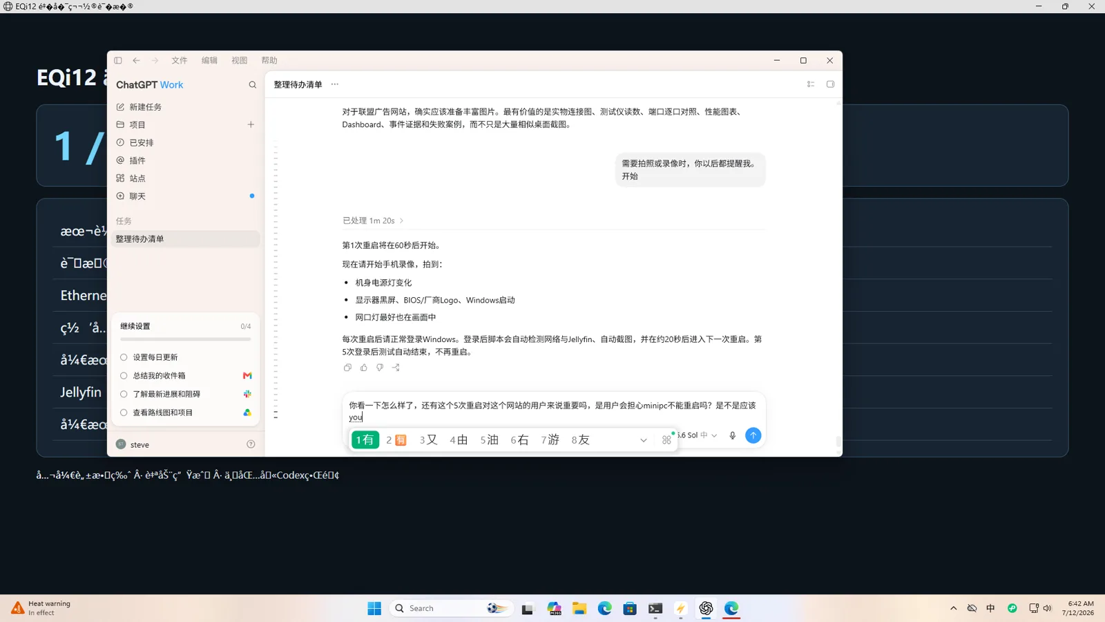
Desktop recovery after AC power restoration with State After G3 set to S0. The system boots automatically without any button press or keyboard input. Jellyfin became available approximately 40.77 seconds after power was restored.
The complete evidence chain includes the BIOS page photograph, physical power-removal video, startup footage and service availability checks.
For the detailed procedure, see the AC power recovery guide. For the full BIOS configuration, see the EQi12 BIOS settings guide.
Common problems and fixes
The system stays off after power returns
- Re-enter BIOS and verify State After G3 is still S0 State.
- Confirm that power was fully removed (all LEDs off, including Ethernet link).
- Check whether the setting offers S0 vs S4 vs S5 — selecting S4 without a hibernation image will fail silently.
- Update the BIOS to the latest revision if the value does not persist.
The system boots but services do not start
Automatic boot restores power, not application state. If Docker, Jellyfin or a database does not start:
- Configure Docker Desktop to auto-start with Windows.
- Set container restart policies to
unless-stopped. - Configure database services to start as system services.
- Verify that the OS does not require an interactive login for services to start.
The setting keeps reverting
Some mini PC BIOS revisions reset custom values after a CMOS battery drain or a firmware update. If State After G3 reverts:
- Update to the latest BIOS from the manufacturer.
- After setting the value, perform a full save-and-exit cycle.
- If it still reverts, the CMOS battery may be depleted or the firmware may have a bug. Report it to the manufacturer.
S0 vs Last State — which is better for a server?
S0 is simpler and more predictable. The server always boots when power returns.
Last State is more flexible but less predictable. If someone shut the server down for maintenance and then a brief outage occurs, Last State keeps it off. S0 would boot it back up, which is usually what you want for availability.
For a home server where availability matters, choose S0. For a workstation where the user controls the power state, Last State may be more convenient.
How this differs from other BIOS vendors
| BIOS vendor | Typical setting name | Common location |
|---|---|---|
| AMI Aptio | State After G3 | Chipset → PCH-IO or Power Management |
| Award | Restore on AC Power Loss | Power Management Setup |
| Phoenix | After Power Loss | Advanced → Power Management |
| Insyde H2O | Power On After Fail | Advanced or Chipset |
The behavior is identical across all vendors. Only the label and menu path change.
UPS and State After G3
State After G3 restores availability after power returns. It does not protect against data loss during the outage itself.
For a home server with databases or active writes:
- Use a UPS to provide battery backup during short outages.
- Configure the UPS software to initiate a graceful shutdown before the battery is exhausted.
- Set State After G3 to S0 so the server boots when utility power returns.
- Test the full cycle: outage → graceful shutdown → power returns → automatic boot → service recovery.
A UPS and State After G3 together provide both data safety and availability. Neither alone is sufficient for a production-like home server.
Related guides
- AC power recovery after outage — complete three-cycle test procedure
- EQi12 BIOS settings for home server — full firmware configuration guide
- Windows home-server build — end-to-end server setup with recovery verification
- Wake-on-LAN setup for Realtek adapters — remote wake configuration
- WOL works from shutdown but not sleep — state-specific troubleshooting